STM32 Memory Protection in Practice - RDP, WRP, Firewall and OTP
Microcontroller datasheets list an impressive set of protection features: readout protection, write protection, proprietary code readout protection, a hardware firewall, one-time-programmable memory, error-correcting flash. Reading the reference manual tells you what each register does. It does not tell you which ones a real product ends up using, in what order they are established, or which ones turn out to be unhelpful once you try.
This article goes through those features on the STM32L4 family, then looks at how one shipping product actually combines them. The example is the COLDCARD bootloader, chosen because the firmware is published in full, including the comments where the developers explain why they rejected one of the features that the marketing material would suggest using.
This article has been made with the help of Claude Code and several custom skills
The features, and what each is for
Six mechanisms are relevant, and they defend against different things. Conflating them is the usual source of confusion.
| Feature | Protects against | Reversible |
|---|---|---|
| RDP (readout protection) | A debugger reading flash out of the chip | Level 1 yes, with mass erase; level 2 never |
| WRP (write protection) | Erasing or reprogramming specific flash pages | Yes, via option bytes |
| PCROP | Reading code as data, even from on-chip | Yes, with constraints |
| Firewall | On-chip code reading a protected region | Not until reset |
| OTP | Rewriting a value once written | No, by construction |
| Flash ECC | Bit errors, whether accidental or induced | Not applicable |
The distinction that matters most is off-chip versus on-chip. RDP and WRP defend the chip against an external attacker with a debug probe. The firewall and PCROP defend one piece of on-chip code against another piece of on-chip code. A design that only sets RDP has said nothing about what its own application layer can read.
Readout protection levels
RDP has three levels, encoded in the option bytes:
- Level 0 is the factory default. Debug access is fully open, and flash can be read and written through JTAG or SWD.
- Level 1 blocks debug access to flash while still allowing the debugger to connect and to read SRAM. Regressing to level 0 triggers a mass erase, which is what makes level 1 useful: the secret is destroyed rather than exposed. On many parts, code running from SRAM under a debugger at level 1 remains a documented risk area.
- Level 2 disables the debug port entirely and locks the boot configuration. It is irreversible. There is no documented path back, no mass-erase escape, and the part will never again accept a debugger or the built-in DFU bootloader.
Level 2 is what a security product wants and what a development team hates, because a level-2 part cannot be debugged, recovered, or reworked. That tension shapes how it gets deployed.
Write protection
WRP marks page ranges as unerasable and unwritable. It is configured through option-byte
registers, WRP1AR and friends on the L4, each holding a start and end page index.
Its role is distinct from RDP. RDP stops an attacker reading secrets out; WRP stops anything, including legitimate firmware update paths and the chip’s own DFU bootloader, from replacing a region. On a device where the first-stage bootloader enforces security policy, WRP is what makes “the bootloader cannot be replaced in the field” a hardware statement rather than a software one.
PCROP
Proprietary Code Readout Protection marks a flash region as execute-only. Instruction fetches succeed; data reads do not. It was designed so a vendor could ship a library to a customer who can call it but not extract it.
The constraint that catches people is that the data bus is blocked even for code inside the protected region. Constants, string literals, and lookup tables placed in a PCROP area are unreadable by the very code that uses them, so any function put there must have its data carefully linked elsewhere. This is documented in ST’s application note AN4758, and it is the reason the feature is less useful than it first appears.
The firewall
The L4 firewall is an on-chip access controller with three configurable segments: a code segment, a non-volatile data segment, and a volatile data segment. Once enabled, any access to a protected segment from outside it resets the processor. Entry is permitted only through a call gate, which the reference manual defines as the first three 32-bit words at the base of the code segment.
Two properties make it strong and awkward in equal measure. It cannot be disabled without a reset, so the protected code cannot be turned off by anything running afterwards. And it has a prearm mechanism: after the protected code returns, the firewall closes, and whether an out-of-segment fetch closes the firewall or resets the chip depends on a prearm bit that the protected code manages itself.
OTP and flash ECC
The OTP area is a small block of one-time-programmable words, 128 slots of 64 bits on this part,
at 0x1FFF7000. Once a slot is written it can never be rewritten, which makes it the natural
place for monotonic state such as a version floor.
Flash ECC is not a security feature by intent, but it becomes one. Each 64-bit word carries 8 additional bits, enough to correct any single-bit error and detect any double-bit error. A detected double-bit error raises a non-maskable interrupt. For an attacker attempting to flip bits in flash, whether by targeted UV-C exposure of the bare die or otherwise, this converts a subtle modification into a crash.
How a product combines them
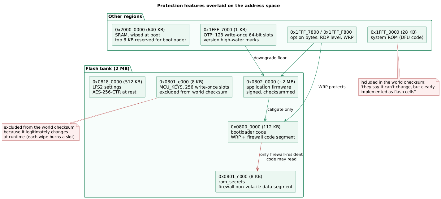
The address space divides into regions with different requirements. The bootloader must be unreplaceable and unreadable; its secrets must be unreadable even by later on-chip code; the application must be replaceable but authenticated; and some regions must change at runtime.
The firewall, configured before anything else
firewall_setup() runs from startup.S before control enters the protected code, and is itself
placed outside the firewall so it can still execute. The configuration covers two segments:
FIREWALL_InitTypeDef init = {
    .CodeSegmentStartAddress    = start,          // aligned at 0x08000300
    .CodeSegmentLength          = len,            // rest of the bootloader
    .NonVDataSegmentStartAddress = BL_NVROM_BASE, // the secrets page
    .NonVDataSegmentLength      = BL_NVROM_SIZE,
    ...
};
The code segment is the bootloader; the non-volatile data segment is the page holding the pairing secrets and key material. Application code reading either address resets the chip.
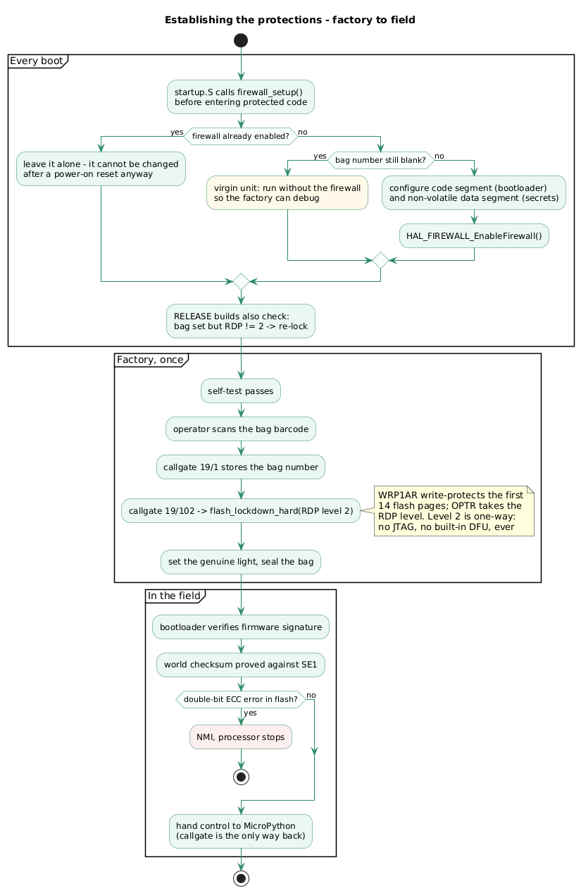
Two conditional paths in that function are worth noting, because they encode deployment reality rather than theory. First, if the firewall is already enabled the function returns immediately, since it cannot be reconfigured after a power-on reset anyway. Second, in release builds it checks whether the unit has been “bagged”:
if(check_all_ones_raw(rom_secrets->bag_number, sizeof(rom_secrets->bag_number))) {
    // ok. still virgin unit -- run w/o security
    return;
}
A unit that has not yet been through factory provisioning runs without the firewall so it can be debugged. Debug builds never enable it at all. This is the pragmatic compromise every such product makes, and it identifies exactly where the weak window lies: a device intercepted between manufacture and bagging is not protected by any of this.
PCROP, considered and rejected
The vendor’s own design document credits PCROP for read-back protection. The code says otherwise.
In flash_lockdown_hard(), the comment is explicit:
// PCRO = Proprietary Code Read-Out (protection)
// - isn't useful to us (doesn't protect data, exec-only code)
// - "In case the Level 1 is configured and no PCROP area is defined,
//    it is mandatory to set PCROP_RDP bit to 1 ..."
// - D-bus access blocked, even for code running inside the PCROP area! (AN4758)
//   So literal values and constant tables and such would need special linking.
The function sets write protection and the RDP level, and does not configure a PCROP region at all. This discrepancy between the documentation and the implementation is a good argument for reading the code when the two are available: a reviewer working from the design document alone would credit the product with a protection it does not use.
The substitution is sound. What PCROP would have provided, preventing on-chip code from reading the bootloader as data, is provided by the firewall, which does protect data and does not have the linking constraint.
The one-way lockdown
flash_lockdown_hard() is what makes the device permanent:
flash_ob_lock(false);
    // lock first 128k-8k against any writes
    FLASH->WRP1AR = (num_pages_locked << 16);
    ...
    uint32_t was = FLASH->OPTR & ~0xff;
    FLASH->OPTR = was | rdp_level_code;
flash_ob_lock(true);
num_pages_locked computes to 14, verified by a static assertion, covering the bootloader region.
The RDP level arrives as a parameter, and the callgate exposes all three values (19/100,
19/101, 19/102) because the factory needs the lower ones during production. Only level 2
ships.
The sequencing is visible in q1.py::scan_and_bag(), the production step where an operator scans
the serialised bag’s barcode:
failed = callgate.set_bag_number(bag_num.encode())
assert not failed

# lock down bootrom against further changes.
callgate.set_rdp_level(2)

# set genuine light
pa.greenlight_firmware()
Bag number, then RDP level 2, then the integrity baseline, then the physical seal. After this the part has no debug port for the rest of its life.
There is also a recovery path in main.c that fires if the two states ever disagree:
if(!check_all_ones(rom_secrets->bag_number, sizeof(rom_secrets->bag_number))
        && !flash_is_security_level2()
) {
    // yikes. recovery: do lockdown... we should be/(thought we were) locked already
    flash_lockdown_hard(OB_RDP_LEVEL_2);
A bagged unit found running below level 2 re-locks itself, on the theory that this indicates either an attack or a production error. The comment underneath records that this path has fired once in the field and left the unit non-functional, which is a fair illustration of how unforgiving one-way security transitions are.
OTP as a version floor
The OTP area holds monotonic version state. record_highwater_version() walks the 128 slots
looking for the first blank one and burns a timestamp into it:
for(int i=0; i<NUM_OPT_SLOTS; i++, otp+=8) {
    if(check_all_ones(otp, 8)) {
        flash_setup0();
        flash_unlock();
            flash_burn((uint32_t)otp, val);
        flash_lock();
        return 0;
    }
}
At boot, get_min_version() scans the same area for the highest recorded value, and
check_is_downgrade() refuses any firmware whose header timestamp falls below it. Because the
slots cannot be rewritten, the floor can only rise, and 128 slots are enough for the product’s
expected lifetime.
This is the correct memory for the job. Anti-rollback state kept in ordinary flash could be erased by whatever can erase flash; state kept in a secure element would require the element to be reachable and authenticated before the decision is made. OTP is neither.
What the integrity check includes
The boot-time checksum reveals which regions the designers consider security-relevant. It covers the firmware, the bootloader including its secrets page, the unprogrammed and filesystem regions, the OTP area, both option-byte banks, the system ROM, and the device serial number.
Two decisions in that list are worth reading. The option bytes are included, so a change to the RDP level or the write-protection configuration alters the checksum and turns the integrity light red. The system ROM is included too, with a comment that gives the reasoning: “System ROM (they say it can’t change, but clearly implemented as flash cells)”. Treating a region documented as immutable as merely probably-immutable costs nothing and covers the case where the documentation is optimistic.
The MCU keys page is excluded, because it legitimately changes at runtime as each wipe consumes a slot. Every exclusion from an integrity measurement is a place where something can change without detection, so the fact that there is exactly one, with a stated reason, is the property to look for when reviewing such a design.
Where these protections stop
Being precise about the residual risk matters more than enumerating the features.
Glitching is unaddressed by all of them. RDP, WRP and the firewall are enforced by logic that
a well-timed voltage or clock glitch may skip. The countermeasure in this code base is timing
jitter: rng_delay() burns a random number of cycles and is sprinkled through the sensitive
paths, including flash setup, PIN hashing and signature verification. It raises the cost of
finding the right moment; it does not make the target disappear. This is the domain of
fault injection work generally.
Factory mode is the weak window. The firewall does not engage on an unbagged unit, and RDP=2 is set at bagging time. A device intercepted before then has none of this, which is why the serialised tamper-evident packaging is part of the security argument rather than packaging.
Level 2 removes your own options too. No debug port means no post-mortem on a returned unit, no recovery from a bootloader bug, and no field repair. The recovery path described above, intended to re-lock a unit found in the wrong state, itself bricked a device. One-way transitions have no undo for the vendor either.
ECC turns modification into denial of service, not into protection. An attacker who can flip two bits cannot subtly alter behaviour, but they can reliably brick the device. Whether that is a good trade depends on the asset; for a wallet with a seed backup it clearly is, and for other products it may not be.
Protection does not equal secrecy. RDP=2 stops a debugger. It does not stop decapsulation and microprobing, which is a different budget and a different threat model. The reason this product splits its seed key across two external secure elements and the processor is precisely that no single one of those, including the processor’s own flash protection, is assumed to hold.
Conclusion
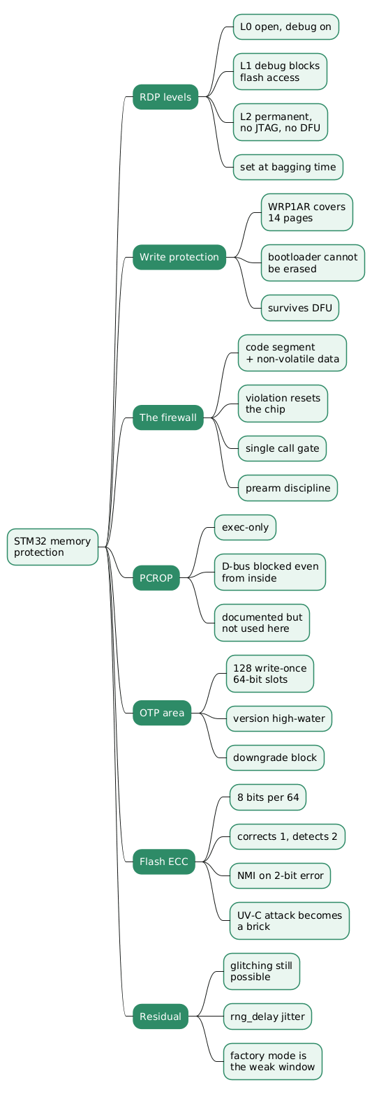
The features divide cleanly by adversary. RDP and WRP answer an attacker with a debug probe; the firewall answers one piece of on-chip code reading another’s secrets; OTP answers rollback; ECC answers induced bit flips. A design that reaches for only one of them has usually answered only one question.
The implementation examined here is worth reading for two reasons beyond the feature list. It shows the ordering that makes the guarantees hold, with the firewall configured before protected code executes and the irreversible lockdown deferred to a single factory step. And it shows a documented feature being rejected on contact with reality, with PCROP set aside because its data-bus restriction makes it impractical for anything but pure code, and the firewall covering the same requirement without that constraint.
The parts that remain uncovered are stated in the same source: glitching is mitigated by timing jitter rather than prevented, unbagged units run without the firewall, and the permanence of level 2 removes the vendor’s own recovery options along with the attacker’s.
Annex
Key Terms
| Term | Definition |
|---|---|
| RDP | Readout protection, an option-byte setting with three levels controlling debug access to flash; level 2 disables the debug port permanently. |
| Mass erase on regression | The behaviour where lowering RDP from level 1 to level 0 erases flash, so the secret is destroyed rather than revealed. |
| WRP | Write protection over flash page ranges, configured in option bytes, preventing erase or reprogramming including by the built-in DFU bootloader. |
| PCROP | Proprietary Code Readout Protection, marking a region execute-only; the data bus is blocked even for code inside the region, which limits it to pure code. |
| Firewall | An on-chip access controller with code, non-volatile data and volatile data segments; out-of-segment access resets the processor and entry is only via the call gate. |
| Call gate | The three 32-bit words at the base of the firewall’s code segment through which protected code may be entered. |
| Prearm | A firewall bit determining whether execution leaving the protected segment closes the firewall or resets the chip. |
| OTP | One-time-programmable memory, 128 slots of 64 bits on this part, suitable for monotonic state such as a minimum-version floor. |
| Flash ECC | Eight error-correction bits per 64-bit flash word, correcting single-bit and detecting double-bit errors, the latter raising a non-maskable interrupt. |
| Bagging | The factory step where a serial number is recorded and the irreversible lockdown is applied, after which the unit is sealed in tamper-evident packaging. |
Security Implementation Checklist
For a firmware design relying on MCU memory protection.
Configuration and ordering
| Check | Security requirement | Failure mode if violated |
|---|---|---|
| ☐ | The firewall (or equivalent) is configured before any code that could read protected regions executes. | A window exists at boot where secrets are readable by later-loaded code. |
| ☐ | Firewall setup code itself lives outside the protected segment. | The configuration routine cannot run, or running it trips the protection. |
| ☐ | Write protection covers every page of the immutable first-stage bootloader. | The update path or the built-in DFU bootloader can replace security-critical code. |
| ☐ | The irreversible RDP transition happens once, at a defined production step, together with recording device identity. | Units ship unlocked, or the lockdown fires unexpectedly in the field. |
| ☐ | Any development escape hatch is keyed to a provisioning state that ships set. | A debug bypass reaches customers. |
Integrity measurement
| Check | Security requirement | Failure mode if violated |
|---|---|---|
| ☐ | The boot integrity check includes the option bytes. | An attacker lowering RDP or clearing WRP is not detected by the integrity check. |
| ☐ | Regions documented as immutable (system ROM) are measured anyway. | A vendor documentation error becomes an undetected modification path. |
| ☐ | Every region excluded from the measurement has a stated reason and changes only through defined operations. | Exclusions accumulate into a place to hide modifications. |
| ☐ | The measurement’s expected value is held outside the processor and cannot be set by it alone. | Modified firmware asserts its own integrity. |
Rollback and monotonic state
| Check | Security requirement | Failure mode if violated |
|---|---|---|
| ☐ | Anti-rollback state lives in write-once memory, not in erasable flash. | Whatever can erase flash can reset the version floor. |
| ☐ | The version floor is consulted before a signed image is accepted, not after. | An old signed image is installed and only then rejected. |
| ☐ | The number of available OTP slots exceeds the expected number of releases. | Anti-rollback silently stops working late in the product’s life. |
Residual risk
| Check | Security requirement | Failure mode if violated |
|---|---|---|
| ☐ | Sensitive decision points include timing jitter against glitch attacks. | A precisely timed fault skips the check entirely. |
| ☐ | Secrets are not assumed safe on the strength of MCU protection alone. | Decapsulation or a protection bypass yields everything at once. |
| ☐ | The unprovisioned window is covered by a physical control such as tamper-evident packaging. | Interception before provisioning defeats every configured protection. |
| ☐ | The consequences of the one-way lockdown for support and repair are accepted deliberately. | Field failures become unrecoverable, including for the vendor. |
Frequently Asked Questions
Q: What is the difference between RDP and the firewall? Both restrict reading flash.
They face opposite directions:
- RDP faces off-chip. It controls what a debugger connected to the JTAG or SWD port can read, and it says nothing about code already running on the processor.
- The firewall faces on-chip. It controls what code running in one region may read from another, resetting the processor on violation, and it says nothing about an external debugger.
A design with RDP=2 and no firewall has a locked debug port and an application layer that can read the bootloader’s secrets freely. That is the gap the firewall exists to close.
Q: Why not use PCROP for the bootloader, since it is designed for exactly this?
Because PCROP is execute-only in a stricter sense than it first appears: the data bus is blocked even for code inside the protected region, per ST’s AN4758. Constants, tables and string literals used by protected code would have to be linked outside it, which is invasive. The comment in this code base states plainly that PCROP “isn’t useful to us”, and the firewall is used instead, since it protects data as well as code and imposes no such linking constraint.
Q: RDP level 2 is irreversible. Why accept that?
Because level 1 is not a security boundary against a patient attacker, and the mass-erase-on-regression behaviour only helps if the secret being protected is inside the erased flash. For a device whose threat model includes a stolen unit and a probe, the debug port has to be gone rather than restricted.
The cost is real and falls on the vendor as much as the attacker: no post-mortem debugging of returned units, no recovery from a bootloader defect, and no field repair. The code examined here contains a recovery path meant to re-lock a mis-provisioned unit, and its own comment records that it left a device non-functional.
Q: Is flash ECC a security feature?
Not by design, but it acts as one. With eight correction bits per 64-bit word, single-bit errors are corrected transparently and double-bit errors raise a non-maskable interrupt that stops the processor. An attacker attempting to induce a specific bit flip, for example by exposing the bare die to UV-C, cannot make a subtle change: they either fail to alter behaviour or they crash the device. That converts a modification attack into a denial-of-service attack, which for a device with a seed backup is a good trade.
Q: Where does this stack of protections still leave an opening?
Three places, all acknowledged in the source:
- Glitching. Voltage or clock faults can skip the logic that enforces these protections. The mitigation here is random timing jitter inserted into sensitive paths, which raises cost without removing the attack.
- The unprovisioned window. The firewall is skipped on units whose bag number is still blank, and RDP=2 is applied at bagging. A unit intercepted before that step has none of these protections, which is why the tamper-evident packaging is part of the security argument.
- Physical attacks below the protection layer. RDP=2 blocks a debugger, not decapsulation and microprobing.
The last is why this particular product does not rely on MCU protection to hold its seed at all, splitting the decryption key across two external secure elements and the processor so that no single failure exposes it.
Q: How should the option bytes themselves be protected?
Measure them. The option bytes are what configure RDP and WRP, so an attacker who could change them would undo everything else. Including both option-byte banks in the boot-time integrity checksum, as this bootloader does, means any change to the protection configuration alters the measurement and fails the integrity check, which is enforced by a secure element rather than by the processor whose protections were changed.
References
Analyzed source
- Coldcard/firmware — analyzed at commit
3238f6fd9977eed786012d0034a04d888c3263bb(release 2026-07-31T0519-v5.6.0), 2026-07-31
Files referenced in that tree
stm32/mk4-bootloader/firewall.c— firewall segment configuration and the bagged-unit conditionstm32/mk4-bootloader/storage.c—flash_lockdown_hard(), WRP setup, PCROP rationale, OTP high-water recordingstm32/mk4-bootloader/main.c— boot-time protection state checkstm32/mk4-bootloader/verify.c— what the integrity checksum coversstm32/mk4-bootloader/dispatch.c— the call gate and the RDP-level methodsdocs/memory-map.md— address map and protection notes
ST documentation
- RM0432 — STM32L4+ Series reference manual
- AN4758 — Proprietary code read-out protection on STM32 microcontrollers
- AN5156 — Introduction to STM32 microcontrollers security
Related articles on this site
- COLDCARD Firmware - Architecture and Security Model
- Firmware Supply Chain - Reproducible Builds and Code Signing
- Hardware Fault Injection Attack
You might also enjoy