PCI PTS HSM v4.0 — How Payment Hardware Security Modules Are Evaluated
Every time a cardholder types a PIN at an ATM or a point-of-sale terminal, the value is encrypted, routed across networks operated by many independent parties, and verified without any of those parties ever seeing the clear-text PIN. The device that makes this possible is the Hardware Security Module (HSM): a tamper-resistant appliance that holds cryptographic keys and performs sensitive operations inside a protected boundary. The PCI PTS HSM Modular Security Requirements v4.0, published by the PCI Security Standards Council in December 2021, is the specification that defines what such a device must do to be approved for the financial payments industry.
This article walks through the structure of that standard: the evaluation modules, the physical and logical controls they impose, the attack-potential methodology used to grade tamper resistance, and the module added in v4.0 for cloud-based HSMs offered as a multi-tenant service.
This article has been made with the help of Claude Code and several custom skills
What a Payment HSM Is and Why PCI Evaluates It
An HSM helps ensure the confidentiality and integrity of financial transactions. Because so much trust rests on it, the standard treats the device as security-critical across its entire life, from manufacturing and shipment through use and decommissioning. The requirements target a defined set of payment processes rather than general-purpose cryptography: PIN processing, 3-D Secure, card verification, card production and personalization, EFTPOS, ATM interchange, cash-card reloading, data integrity, chip-card transaction processing, key generation, and key injection.
The document is explicit about its own limits. It is a risk-reduction instrument, not a guarantee. The requirements are described as the minimum acceptable criteria, defined so that the cost of an attack outweighs its benefit. They are not meant to eliminate fraud but to reduce its likelihood and contain its consequences. The controls are derived from existing ISO, ANSI, NIST, and FIPS standards together with practices recognized across the payments industry, so an HSM evaluation is in large part a check that a device correctly composes those underlying primitives.
Scope also has a hard boundary in time. The standard covers device management only up to receipt at the point of deployment. After that, responsibility passes to the acquiring financial institution and its agents, governed by the operating rules of the payment brands and by companion documents such as the PCI PIN Security Requirements.
The Modular Structure of the Standard
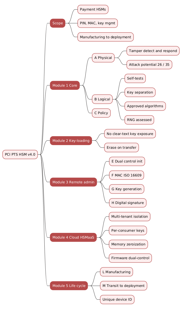
Version 4.0 is organised into five evaluation modules. A device is assessed against the modules that match its functionality, so a simple key-loading tool and a full cloud HSM service are judged by different subsets of the same catalogue.
- Module 1 — Core Requirements. Physical security (Section A), logical security (Section B), and policy and procedures (Section C). Every HSM must meet these.
- Module 2 — Key-Loading Devices. Section D, for devices that generate or transfer keys into other cryptographic devices.
- Module 3 — Remote Administration. Sections E through H, covering logical security of remote management, message authentication, key generation, and digital-signature functionality.
- Module 4 — Cloud-based HSMs as a Service. Sections I, J, and K, the multi-tenant and remote-management module that is new in v4.0.
- Module 5 — Life-Cycle Security. Sections L and M, covering the device during manufacturing and in transit between the manufacturer and the point of initial deployment.
Each requirement is written as a testable statement that a laboratory answers Yes, No, or N/A. Successful compliance testing and PCI SSC approval result in the device being listed publicly, using the commercial identifiers the vendor supplies on the required device-information forms.
Module 1, Section A — Physical Security and Attack Potential
The physical requirements protect against an attacker who has the device in hand. The central mechanism is tamper detection and response: requirement A1 states that the device must detect penetration attempts and respond with automatic and immediate erasure of any sensitive data it holds, so that recovering that data becomes infeasible. Zeroization is the defining behaviour of a payment HSM; a device that could be opened and read is worthless regardless of the algorithms it runs.
The requirements grade the difficulty of an attack using an attack-potential score, a methodology inherited from the Common Criteria and defined in the accompanying PCI HSM Derived Test Requirements. The score aggregates factors such as the time required, the expertise and knowledge of the target needed, the window of opportunity, and the equipment involved. Two thresholds appear throughout the standard: a total value for identification and initial exploitation combined, and a smaller minimum for the initial exploitation phase alone. The distinction matters because finding an attack for the first time (identification) is often far harder than repeating it, and a control is only meaningful if repeating a discovered attack is also costly.
The core physical thresholds are:
- A1 and A3. Penetration to reach internal sensitive areas, and unauthorized modification or substitution of sensitive functions, must each require an attack potential of at least 26, with a minimum of 13 for initial exploitation.
- A4. Determining any PCI-related secret or private key by penetrating the device must require an attack potential of at least 35, with a minimum of 15 for initial exploitation.
The higher bar for keys in A4 reflects that key extraction is the worst outcome: a recovered key can compromise every transaction it ever protected. Two further requirements close side channels. A2 requires that the device is not compromised by altering environmental conditions, for example by driving temperature or supply voltage outside the stated operating ranges, a class of attack that tries to induce faults or force the device out of its protected state. A5 requires that emanations, including power fluctuations and timing, cannot be used to recover PINs, account data, or keys, which is the standard’s requirement against side-channel and power-analysis attacks.
Module 1, Section B — Logical Security
Where Section A keeps an attacker out physically, Section B constrains what the device will do even for a legitimate interface. Nineteen requirements define the functional behaviour, and several of them encode principles that recur across all of cryptographic engineering.
The diagram below shows how these controls surround the sensitive material inside the boundary.
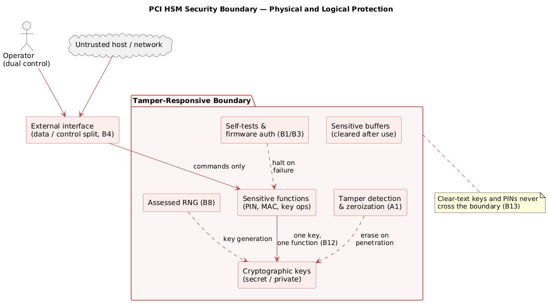
Integrity of the device itself. B1 requires self-tests, run when the device becomes pre-operational and at least once per day, that check firmware authenticity, look for signs of tampering, and detect a compromised state, with failure handling consistent with FIPS 140-2/140-3. B2 requires that the device is not influenced by logical anomalies such as unexpected command sequences, unknown commands, commands in the wrong mode, or malformed parameters that could trick it into outputting sensitive information. B3 requires that firmware updates are cryptographically authenticated and that any update failing the authenticity check is rejected and deleted, with integrity, mutual authentication, and replay protection when the update arrives over a network.
Separation and least privilege. B4 keeps interfaces logically separate by distinguishing data from control on inputs and data from status on outputs. B16 requires that where a device runs multiple applications, or acts as several logical devices through virtualization, one application cannot interfere with or tamper with another or with the firmware. B17 requires that the operating system and firmware contain only the components necessary for operation, configured securely and running with least privilege.
Key handling. These requirements carry most of the module’s weight. Several of them work together to enforce that keys are used only as intended and never leak:
- B7 — key entry. Private and secret keys may be entered only by accepted techniques. Clear-text keys may enter only by a direct interface, never manually or over a network; clear-text key components may enter manually or directly but not over a network; enciphered keys and components may enter by any of the three.
- B12 — key separation. Each cryptographic key may be used for only a single function. It must not be possible to encrypt or decrypt arbitrary data with a PIN-encryption key, an account-data key, a data-encrypting key, or a key-encrypting key, and the key-usage information cannot be altered to broaden how a key may be used.
- B13 — no clear-text leakage. There is no mechanism to output private or secret clear-text keys, to encrypt a key under a key that might itself be disclosed, or to move a clear-text key from a higher-security component into a lower-security one. Cryptographic functions must not output clear-text critical security parameters to components that could weaken security.
- B11 — fail secure. If keys inside the boundary are invalidated for any reason, such as tamper or long-term loss of power, the device fails in a secure manner.
Approved primitives.
- B9 requires accepted algorithms, modes, and key sizes;
- B8 requires that any random number generator used for security over sensitive data has been assessed to produce sufficiently unpredictable output, tying back to NIST SP 800-90A and the statistical testing of SP 800-22.
- B10 requires key management conforming to ISO 11568 and/or ANSI X9.24, and mandates support for key blocks as defined in DTR 77, the interoperable, cryptographically bound key-wrapping format standardised as ANSI X9.143 (formerly TR-31).
- B14 requires that a PIN-processing device meets ISO 9564 for PIN management and uses an ISO 9564 PIN-encryption technique.
- B15 requires cryptographic mechanisms for secure logging to support auditing,
- and B19 requires that a device with both a PCI and a non-PCI mode keeps their keys separate, signals which mode is active, and demands dual authentication to switch.
Section C adds a single but important policy requirement, C1: the vendor must publish a security policy that describes correct use, defines the roles and the services available to each role in a deterministic tabular format, and confirms that the device performs only its designed functions with no hidden functionality.
Modules 2 and 3 — Key Loading, MAC, Key Generation, and Signatures
Module 2 (Section D) covers key-loading devices. Its requirements ensure that a device generating or transferring keys never exposes them in the clear: D1 requires that when generating asymmetric key pairs or secret keys, the private or secret value and its precursors are never visible in clear-text during generation; D2 requires that keys not used by the device itself, together with their seed elements, are deleted immediately after transfer; D3 requires that the device retains nothing that could disclose a key it has already transferred into another device; and D5 requires that once loaded with keys, the device cannot have its functional capabilities modified without erasing those keys or detectably flagging the change before the next key load.
Module 3 covers remote administration and optional functional blocks. Section E governs logical security of remote management: E1 requires that the device cannot enter operational service until initialization is complete, and E2 requires that operator functions able to influence security, such as enabling or disabling functions or changing authentication codes, are permitted only under dual or multiple control, with the interface designed so it is highly unlikely the device is inadvertently left in a sensitive state.
The three remaining sections apply only to devices offering the corresponding functionality.
- Section F — message authentication. MAC length must follow ISO 16609 (F2), two-key MAC techniques must follow ISO 16609 (F3), a device that displays a computed MAC only confirms or denies a supplied MAC rather than outputting the clear-text value (F1), and a unidirectional MAC key is used for only one direction, either verifying received text or generating a MAC for transmitted text (F4).
- Section G — key generation. Unauthorized removal from the operational location is deterred either by erasing keys on removal or by making removal pointless through tamper resistance (G1); no clear-text key is output except under dual control, enforced for example by two passwords within five minutes or two physical keys inserted concurrently (G2); and proprietary functions must either be equivalent to a series of approved functions or be restricted by key separation so they cannot operate on the keys of standard functions (G4).
- Section H — digital signatures. The asymmetric key pair is generated inside the signature device, the private key leaves the original device only under dual control, and its use is controlled (H1); and the binding between a public key and the identity of the private-key owner is determinable for audit through public-key certificates from an authorized authority or an equivalent irrefutable mechanism (H2).
Module 4 — Cloud-Based HSMs as a Service
The one substantive addition in v4.0 is Module 4, which addresses HSMs delivered as a multi-tenant cloud service. This module recognises a deployment model that the earlier standard did not anticipate: many independent customers, called HSM Solution Consumers, share physical hardware while each retains sole authority over its own keys. The problem it solves is isolation between tenants who do not trust one another, on infrastructure operated by a third party.
The module introduces a vocabulary for the layers involved. The HSM processing element is the certified cryptographic engine that actually performs operations; the HSM virtualization system switches and routes secure channels between consumers and processing elements; and the HSM Solution Consumer is the tenant who owns a set of keys. The diagram below shows how a single processing element serves two consumers without letting either reach the other’s keys.
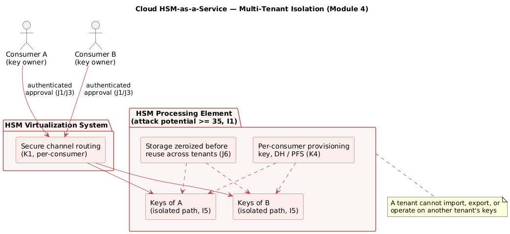
Section I sets the physical baseline for cloud: the processing element must meet all HSM physical and logical requirements to an attack potential of at least 35 (I1), and clear-text secret and private keys must be processed in execution paths and memory areas isolated from the keys of any other consumer or from code outside the evaluation scope (I5).
Section J sets the logical rules for tenant sovereignty:
- Keys cannot be imported or exported without cryptographically authenticated approval from their owner (J1), and operations on a consumer’s keys require a cryptographically verifiable request from that owner (J3).
- Clear-text sensitive data, including PINs and secret or private keys, never leaves a processing element, and clear-text PAN data is handled only within a processing element or a PCI DSS compliant environment (J4).
- All storage, including registers, cache, and scratchpad memory, must be cleared of one consumer’s sensitive data before processing another consumer’s keys, accounting for any memory virtualization or wear-levelling (J6).
- Firmware updates are signed under dual control using keys held in a FIPS 140-2/3 level 3 or PCI-approved HSM, and the update mechanism forbids installing firmware older than the current version unless all keys are first erased (J8), an explicit anti-rollback control.
Section K governs provisioning and management. Each processing element establishes a unique provisioning key per consumer using a key-agreement process such as Diffie-Hellman that provides perfect forward secrecy (K4), so that compromise of long-term material does not expose past session keys.
Tamper keys protecting more than one consumer’s keys must be unique per processing element, generated internally with an approved RNG, and never exportable (K5). The solution must be able to suspend a consumer’s key access on any processing element (K6), must publish a security policy describing how services are provided and how keys can be securely deprecated (K9), and must operate a public vulnerability management and disclosure policy (K10).
Module 5 — Life-Cycle Security
The final module protects the device before it ever reaches a customer, on the principle that a device tampered with in the factory or in transit defeats every runtime control. It establishes a chain of custody from design to initial key loading, illustrated below.
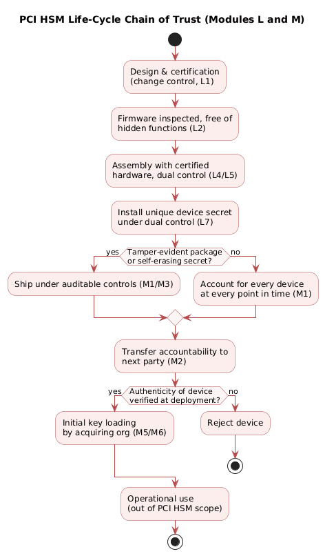
Section L covers manufacturing. Change-control procedures trigger re-certification when the device’s physical or functional security characteristics change (L1); firmware is inspected through a documented, auditable process and verified free of hidden or undocumented functions (L2), then protected against unauthorized modification throughout the manufacturing lifecycle using dual control or cryptographic authentication (L3). Hardware assembly uses only the certified components with no unauthorized substitutions (L4), and production software is transported and loaded under dual control (L5). A pivotal control is L7: the device is authenticated at the facility of initial deployment by means of a secret placed in it during manufacturing, unique to each device, unknown and unpredictable to any person, and installed under dual control, or by an authenticated public-key method. Authentication by secret information is mandatory in HSM v4.
Section M covers the interval between the manufacturer and initial deployment. The device is protected by tamper-detection features with authenticity-validation instructions provided to customers, and where that is not possible it is shipped and stored under auditable controls that can account for every device at every point in time (M1).
Accountability is formally transferred from one party to the next along the shipping chain, and in the absence of an agreement the vendor remains responsible (M2).
In transit the device is shipped in tamper-evident packaging, or carries a secret that self-erases on any physical or functional alteration and can be verified by the key-loading facility but not determined by unauthorized personnel (M3).
Each device carries a unique visible identifier, its model name and hardware version, retrievable by a secure, cryptographically protected query (M7), and the vendor maintains a manual recording the full life cycle of the device’s security-related components, including production data, physical whereabouts, repair, removal from operation, and loss or theft (M8).
Conclusion
The PCI PTS HSM v4.0 requirements describe a device defined by what it refuses to do. It refuses to reveal a clear-text key, refuses to use a key for a purpose other than the one assigned, refuses to run firmware it cannot authenticate, and refuses to survive a physical intrusion with its secrets intact. The five modules apply this posture across every stage: physical and logical controls at runtime, dedicated rules for key loading and remote administration, tenant isolation for cloud deployments, and a chain of custody that reaches back to the factory. The v4.0 addition of the cloud module extends the same key-separation and zeroization principles from a single sealed box to shared infrastructure, where the boundary being defended is now between tenants rather than only between the device and the outside world.
For anyone integrating, procuring, or auditing payment cryptography, the standard is useful as a checklist of the properties that matter, and as a reminder that the security of a payment key depends as much on manufacturing, shipping, and multi-tenant isolation as on the algorithm that uses it.
Annex
Key Terms
| Term | Definition |
|---|---|
| HSM | Hardware Security Module, a tamper-resistant device that stores cryptographic keys and performs sensitive operations inside a protected boundary. |
| PCI PTS | PIN Transaction Security, the PCI Security Standards Council programme under which payment devices, including HSMs, are evaluated and approved. |
| Tamper response / zeroization | The automatic and immediate erasure of sensitive data when a device detects a physical intrusion, making the data infeasible to recover. |
| Attack potential | A numeric score, inherited from the Common Criteria, that grades the difficulty of an attack by combining time, expertise, target knowledge, opportunity, and equipment. |
| Key separation | The rule that each cryptographic key may be used for exactly one function, so a PIN key cannot decrypt arbitrary data or act as any other key type. |
| Key block | A cryptographically bound, interoperable key-wrapping format (DTR 77 / ANSI X9.143, formerly TR-31) that binds a key to its usage attributes. |
| Dual control | A control requiring two or more authorized operators to act together, so no single person can perform a sensitive operation such as outputting a clear-text key. |
| Clear-text key | A cryptographic key in unencrypted form; the standard forbids exposing such a key outside the protected boundary of the device. |
| HSM Solution Consumer | In the cloud module, a tenant that owns a set of keys and retains sole cryptographic authority over their use on shared infrastructure. |
| Perfect forward secrecy | A property of key agreement, such as Diffie-Hellman, where compromise of long-term keys does not expose previously established session keys. |
Requirements Checklist
The standard is written as a form: a laboratory marks each requirement Yes, No, or N/A. The tables below condense every requirement into a one-line checklist, grouped by section, so the catalogue can be used directly as an evaluation or procurement aid. A device is assessed only against the sections that match its functionality, and an N/A is acceptable when a requirement’s characteristic is genuinely absent or another option provides equivalent coverage.
Module 1, Section A — Physical Security
| Check | # | Requirement |
|---|---|---|
| ☐ | A1 | Tamper-detection and response erase sensitive data on penetration; attack potential ≥ 26 (≥ 13 for exploitation). |
| ☐ | A2 | Security is not compromised by altering environmental or operational conditions (temperature, voltage). |
| ☐ | A3 | Sensitive functions used only in protected areas; modification requires attack potential ≥ 26 (≥ 13). |
| ☐ | A4 | Determining a secret or private key by penetration requires attack potential ≥ 35 (≥ 15). |
| ☐ | A5 | Emanations (power, timing) cannot be used to recover PINs, account data, or keys. |
Module 1, Section B — Logical Security
| Check | # | Requirement |
|---|---|---|
| ☐ | B1 | Self-tests on start-up and at least daily; fail secure on failure, consistent with FIPS 140-2/140-3. |
| ☐ | B2 | Functionality is not influenced by logical anomalies (bad command sequences, wrong mode, malformed parameters). |
| ☐ | B3 | Firmware updates are cryptographically authenticated; failed updates are rejected and deleted. |
| ☐ | B3.1 | Applications loaded into the device are authenticated consistently with B3. |
| ☐ | B4 | Interfaces are logically separate: data from control on inputs, data from status on outputs. |
| ☐ | B5 | Internal buffers holding sensitive data are cleared once no longer needed (completion, timeout, error). |
| ☐ | B6 | Access to sensitive services requires authentication; entering or exiting them does not reveal sensitive data. |
| ☐ | B7 | Private and secret keys are entered only by accepted techniques (clear-text only by direct interface). |
| ☐ | B8 | Any random number generator is assessed to produce sufficiently unpredictable output. |
| ☐ | B9 | The device uses accepted algorithms, modes, and key sizes. |
| ☐ | B10 | Key management conforms to ISO 11568 / ANSI X9.24 and supports key blocks (DTR 77). |
| ☐ | B11 | Invalidated keys (tamper, power loss) cause the device to fail in a secure manner. |
| ☐ | B12 | Each key is used for a single function; key-usage information cannot be broadened. |
| ☐ | B13 | No mechanism outputs clear-text keys or transfers a clear-text key to a lower-security component. |
| ☐ | B14 | PIN-processing devices meet ISO 9564 for PIN management and PIN encryption. |
| ☐ | B15 | Cryptographic mechanisms support secure logging for auditing. |
| ☐ | B16 | Multiple applications or virtualization enforce separation; none can tamper with another or the firmware. |
| ☐ | B17 | The OS/firmware contains only necessary components, configured securely, running with least privilege. |
| ☐ | B18 | The device can return its unique device ID. |
| ☐ | B19 | Dual PCI / non-PCI mode devices keep keys separate, signal the active mode, and require dual auth to switch. |
Module 1, Section C — Policy and Procedures
| Check | # | Requirement |
|---|---|---|
| ☐ | C1 | A published security policy defines roles and per-role services in a deterministic table; no hidden functionality. |
Module 2, Section D — Key-Loading Devices
| Check | # | Requirement |
|---|---|---|
| ☐ | D1 | Generated private or secret keys and their precursors are never visible in clear-text during generation. |
| ☐ | D2 | Keys not used by the device, with their seed elements, are deleted immediately after transfer. |
| ☐ | D3 | The device retains nothing that could disclose a key already transferred into another device. |
| ☐ | D4 | A multi-component device cannot move a key from a higher-security domain to a lower-security one. |
| ☐ | D5 | Once loaded, functional capabilities cannot change without erasing keys or detectably flagging the change. |
Module 3, Section E — Remote Administration (Logical)
| Check | # | Requirement |
|---|---|---|
| ☐ | E1 | The device cannot enter operational service until initialization (keys and material loaded) is complete. |
| ☐ | E2 | Security-influencing operator functions are permitted only under dual or multiple control. |
Module 3, Section F — Message Authentication
| Check | # | Requirement |
|---|---|---|
| ☐ | F1 | The device outputs only a MAC confirm/deny, never the clear-text computed MAC; it displays the key identity. |
| ☐ | F2 | The generated or verified MAC length is in accordance with ISO 16609. |
| ☐ | F3 | Two-key MAC generation or verification follows ISO 16609. |
| ☐ | F4 | A unidirectional MAC key is used for only one direction (verify received, or generate for transmitted). |
Module 3, Section G — Key Generation
| Check | # | Requirement |
|---|---|---|
| ☐ | G1 | Unauthorized removal erases keys, or tamper resistance makes removal pointless. |
| ☐ | G2 | No clear-text key is output except under dual control (two passwords within five minutes, or two physical keys). |
| ☐ | G3 | Operator functions such as manual control-data input or moving the device require sensitive states. |
| ☐ | G4 | Proprietary functions equal a series of approved functions, or are key-separated from standard functions. |
Module 3, Section H — Digital Signature
| Check | # | Requirement |
|---|---|---|
| ☐ | H1 | The key pair is generated inside the device; the private key is exported only under dual control, with controlled use. |
| ☐ | H2 | The public-key-to-owner binding is determinable for audit (certificates from an authorized CA or equivalent). |
Module 4, Section I — Cloud Physical Security
| Check | # | Requirement |
|---|---|---|
| ☐ | I1 | The HSM processing element meets all physical and logical requirements to attack potential ≥ 35 (≥ 15). |
| ☐ | I2 | Virtualization systems run in a controlled environment or protect sensitive data to attack potential ≥ 26 (≥ 13). |
| ☐ | I3 | Virtualization systems routing secure channels manage keys within a tamper-responsive system (≥ 26, ≥ 13). |
| ☐ | I4 | A virtualization system sharing the processing element’s execution environment meets its security requirements. |
| ☐ | I5 | Clear-text keys are processed in execution paths and memory isolated from other consumers and out-of-scope code. |
Module 4, Section J — Cloud Logical Security
| Check | # | Requirement |
|---|---|---|
| ☐ | J1 | Consumer keys cannot be imported or exported without the owner’s cryptographically authenticated approval. |
| ☐ | J2 | Each processing element requires cryptographic authentication before provisioning keys or opening a secure channel. |
| ☐ | J3 | Operations on a consumer’s keys require a cryptographically verifiable request from the key owner. |
| ☐ | J4 | Clear-text PINs and keys never leave a processing element; clear-text PAN stays in a processing element or PCI DSS scope. |
| ☐ | J5 | All key-management operations on a consumer key, including key-wrap validation, occur within the processing element. |
| ☐ | J6 | Storage is cleared of one consumer’s data before another’s keys are processed, accounting for wear-levelling. |
| ☐ | J7 | Each solution provides a verifiable unique ID with hardware and firmware versions; firmware updates are logged. |
| ☐ | J8 | Firmware is signed under dual control; installing older firmware is prevented unless all keys are erased. |
Module 4, Section K — Cloud Provisioning and Management
| Check | # | Requirement |
|---|---|---|
| ☐ | K1 | Connections use secure channels, independent per interface and per consumer. |
| ☐ | K2 | Updates affecting a consumer are approved first; consumer-configurable settings are isolated from other consumers. |
| ☐ | K3 | Compliance-affecting configuration changes are cryptographically authenticated and cannot affect another consumer. |
| ☐ | K4 | Each consumer gets a unique provisioning key via key agreement (e.g. Diffie-Hellman) with perfect forward secrecy. |
| ☐ | K5 | Tamper keys protecting more than one consumer are unique per processing element, internally generated, non-exportable. |
| ☐ | K6 | Access to a consumer’s keys can be disabled or suspended on any processing element. |
| ☐ | K7 | A consumer can keep an external log of all operations and which components performed them. |
| ☐ | K8 | Processing elements that may share a consumer’s keys are kept in a controlled environment. |
| ☐ | K9 | A public security policy describes services, authentication, and secure deprecation of consumer keys. |
| ☐ | K10 | A public vulnerability management and disclosure policy is in place. |
Module 5, Section L — Life Cycle During Manufacturing
| Check | # | Requirement |
|---|---|---|
| ☐ | L1 | Change control triggers re-certification when physical or functional security characteristics change. |
| ☐ | L2 | Firmware is inspected through an auditable process and verified free of hidden or undocumented functions. |
| ☐ | L3 | Certified firmware is protected against modification throughout manufacturing (dual control or crypto auth). |
| ☐ | L4 | Assembly uses only certified hardware components, with no unauthorized substitutions. |
| ☐ | L5 | Production software is transported, stored, and loaded under dual control. |
| ☐ | L6 | Between production and shipment, devices are stored in a protected area or sealed tamper-evident packaging. |
| ☐ | L7 | The device is authenticated at deployment via a unique manufacturing secret (mandatory in v4) or public-key method. |
| ☐ | L8 | Development-security measures and documentation protect the integrity of security-related components. |
| ☐ | L9 | Controls govern the repair process and subsequent inspection and testing. |
Module 5, Section M — Between Manufacturer and Deployment
| Check | # | Requirement |
|---|---|---|
| ☐ | M1 | The device has tamper detection with authenticity-validation docs, or ships under fully accountable controls. |
| ☐ | M2 | Accountability is formally transferred along the shipping chain; absent an agreement, the vendor remains responsible. |
| ☐ | M3 | In transit the device uses tamper-evident packaging and/or a secret that self-erases on alteration. |
| ☐ | M4 | Development-security documentation lets the deployment facility assure component authenticity. |
| ☐ | M5 | If the manufacturer loads initial keys, it verifies the authenticity of security-related components. |
| ☐ | M6 | If it does not, the manufacturer provides the deployment facility the means to verify authenticity. |
| ☐ | M7 | Each device has a unique visible identifier (model and hardware version), also retrievable by secure query. |
| ☐ | M8 | The vendor maintains a manual recording the full life cycle (production, whereabouts, repair, removal, loss/theft). |
Frequently Asked Questions
Q: What is the single most important behaviour that distinguishes a payment HSM from ordinary hardware?
Tamper response, also called zeroization. Requirement A1 states that the device must detect physical penetration and respond by automatically and immediately erasing any sensitive data, so that recovering it becomes infeasible. Because the whole trust model assumes an attacker may eventually gain physical possession of the device, a payment HSM is only as valuable as its guarantee that a break-in destroys the keys before they can be read. Every other physical control exists to raise the cost of reaching that sensitive material in the first place.
Q: What does “attack potential of at least 26, with a minimum of 13 for initial exploitation” actually mean?
Attack potential is a score that grades how hard an attack is, aggregating factors such as time, required expertise, knowledge of the device, window of opportunity, and equipment. The two numbers separate two phases. The larger value covers identification plus initial exploitation, that is, discovering a working attack and carrying it out the first time. The smaller value is the floor for initial exploitation alone, meaning how hard it is to repeat the attack once known. Requiring both stops a device from passing on the strength of a hard-to-find attack that becomes trivial to repeat. For secret and private keys, requirement A4 raises the combined threshold to 35 with a floor of 15, because key recovery is the highest-impact outcome.
Q: Why does the standard insist that each key be usable for only one function?
This is key separation, requirement B12. If a single key could both encrypt PINs and decrypt arbitrary data, an attacker could feed chosen ciphertext through the device and use the PIN-encryption key as a general-purpose decryption oracle, defeating the confidentiality of everything it protects. By binding each key to one function, and forbidding any change to the key-usage metadata that would widen its use, the device prevents these cross-purpose attacks. Requirement B10’s mandate for key blocks reinforces this at the format level: the usage attributes are cryptographically bound to the key so they cannot be stripped or altered in transit.
Q: How does the cloud module keep one tenant’s keys away from another’s on shared hardware?
Module 4 layers several controls. Physically, clear-text keys of different consumers must be processed in isolated execution paths and memory areas (I5), and any storage must be zeroized before it is reused for a different tenant, accounting for memory virtualization and wear-levelling (J6). Logically, keys cannot be imported, exported, or operated on without a cryptographically authenticated approval from their owner (J1, J3). For provisioning, each consumer gets a unique provisioning key established by a key-agreement process with perfect forward secrecy (K4), and tamper keys protecting more than one consumer are unique per processing element and never exportable (K5). Together these ensure a tenant can neither reach nor influence another tenant’s keys.
Q: The standard covers a device only up to the point of deployment. Combining the life-cycle and logical modules, why is that boundary defensible?
The life-cycle module (Sections L and M) builds a chain of custody from design through initial key loading: firmware is inspected for hidden functions, assembly uses only certified components, and a unique device secret is installed under dual control during manufacturing (L7) so the deployment facility can authenticate the device before trusting it. In transit the device is either in tamper-evident packaging or carries a self-erasing secret (M3), and accountability passes formally from party to party (M2). By the time keys are loaded, the device has proven its authenticity and its integrity is intact. From that point the runtime logical controls take over: self-tests (B1), authenticated firmware updates with anti-rollback (B3, and J8 in cloud), fail-secure behaviour on tamper or power loss (B11), and the operational responsibility shifts to the acquiring institution under the PCI PIN Security Requirements. The two halves meet cleanly because the life-cycle controls guarantee a trustworthy starting state and the logical controls preserve it thereafter.
Q: What changed between v3.0 and v4.0?
The headline change is the addition of Module 4, “Cloud-based HSMs as a Service — Multi-tenant Usage and Remote Management Security Requirements,” which introduces the vocabulary of processing elements, virtualization systems, and solution consumers, and the isolation, provisioning, and disclosure rules that govern them. Beyond that, the earlier version (v3.0, June 2016) had already added requirements for key-loading devices and remote administration platforms and required validation of device management information submitted by vendors. Some individual requirements were also tightened; for example, authentication of the device by secret information became mandatory in HSM v4 under L7.
References
- PCI Security Standards Council — Document Library — source of the PCI PTS HSM Modular Security Requirements v4.0 (December 2021) and related PCI standards.
- PCI PIN Transaction Security (PTS) programme — approved-device listings and the PTS evaluation framework.
- ANSI X9.24 — Retail Financial Services Symmetric Key Management — symmetric key-management techniques referenced by requirement B10.
- ANSI X9.143 — Interoperable Secure Key Block Specification — the key-block format (formerly TR-31) mandated via DTR 77.
- ISO 9564 — PIN Management and Security — PIN-encryption techniques required by B14.
- ISO 11568 — Financial Services Key Management (Retail) — key-management framework referenced by B10.
- ISO 16609 — Requirements for message authentication using symmetric techniques — MAC requirements referenced by Section F.
- NIST SP 800-90A Rev. 1 — Random Number Generation Using Deterministic Random Bit Generators — DRBG guidance behind requirement B8.
- FIPS 140-3 — Security Requirements for Cryptographic Modules — self-test and failure-handling reference for B1.
You might also enjoy